Overview Tab
The DPM Manager User Interface is used to manage the DPM settings.
When you open the DPM Manager, the user interface displays, with the Overview tab selected.
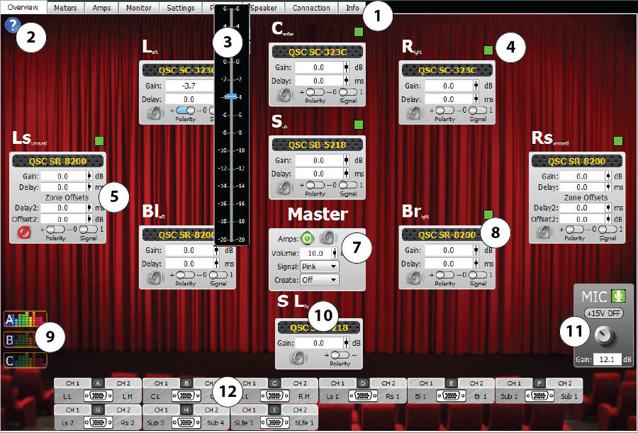
- Tabs
- Overview – Displays a high-level overview of the DPM selected in the Device list along with some basic loudspeaker adjustments. Default screen when DPM Manager is started.
- Meters – The Meters screen displays level meters representing the inputs and outputs of the DPM.
- Amps – The Amps screen
allows you to select and configure amplifiers , to monitor their inputs and outputs, and various other amplifier parameters.
- Monitor – The Monitor screen allows you to select which source you would like to monitor through the monitor loudspeaker or headphone jack. You can monitor the inputs, outputs, amplifiers, or microphone source.
- Settings – The Settings screen provides various setup controls.
- Presets – The Presets screen gives you the ability to customize various audio and control presets, which can be recalled to easily reconfigure your DPM to a desired setup.
- Speaker – The Speaker screen provides the ability to load loudspeakers, set EQ for each channel and in three different scenarios (A, B, C), and more.
- Connection – The Connection screen is used for Network setup, Serial Port setup, and Automation GPI Configuration.
- Info – The Info screen provides System, Version, Fault, Rail, and Automation status information.
- Help Button – Click to display the help for the current screen. Available for all screens.
- Fader Pop-up – Displays any time the fader icon for Gain, Volume, Delay, or Offset is clicked and held.
- Indication of audio signal input to the associated channel.

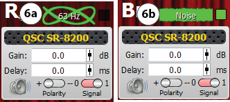
- Channel Controls
There is one control box for each channel and a Master control box.
NOTE: You can use the fader  , or click the digital readout and use your keyboard to enter the gain, delay, and offsets. Not all of the channels have the same controls.
- Gain – (minus) -20 to (positive) +6 dB for each channel.
- Delay – 0 to 130 ms
- Delay2 – 0 to 130 ms (Delay2 is only available for the Left Surround and Right Surround channels.
- Offset2 – (minus) -20 to (positive) +6 dB for (Offset2 is only available for the Left Surround and Right Surround channels. Note: Additional sub zones can be configured in Speaker tab.
- Mute – on
 / off
/ off 
- Polarity – (positive) +
 and (negative) -
- Signal – used to manually turn the signal (Tone or Pink Noise) on
 / off to the selected channel.
- Indication and type of signal sent to the channel.
- Tone Signal
- Pink Noise
- Master Controls
- Amps – Turns on
 / off
/ off  all DataPort amps connected to the DPM.
 - Master Mute – on / off Mutes or unmutes all audio outputs.
- Volume – Controls the overall volume of all audio outputs.
- Signal
- Pink Noise
- Create
- Off – Signal generator is off.
- On – Turns the Signal generator on without sending the signal to any channels. You can then select the channels individually using the Signal switch on the channel control boxes.
- Rotate – Sends the selected signal to all the channels one at a time, starting from Center and rotating clockwise, ending with the Sub channel.
- Tone
- Create
- Off – Signal generator is off
- 63 Hz, 100 Hz, 1000 Hz, 5000 Hz
- Sweep – The signal generator cycles through frequencies ranging from 63Hz to 10kHz in 1/3 octave steps.
- Sub Sweep – The signal generator cycles through frequencies 25 Hz to 80 Hz in 1/3 octave steps.
- Loudspeaker Model – Displays the name/model of QSC Intrinsic Correction™ loudspeaker or a custom loudspeaker assigned to the channel. Click this area to go to this channel’s settings on the Speakers tab.
- EQ Scenarios – Click A, B, or C to recall the user-defined EQ scenario you want.
- SLfe (Surround Low Frequency Effects) – A mix of the four surround channels’ low frequency content is sent to this loudspeaker. The mix is controlled on the Speakers tab.
- MIC Controls – Provides Mute button, +15 V phantom power, Gain control with digital readout, for the Microphone input XLR on the rear of the DPM. This control is only available when the active preset uses the Mic input.
- DataPort Connectors – Shows the current configuration of the DataPort outputs based on the speaker Crossover as defined on the Settings tab as well as user selections on the Amps tab. For example, if the Screen Configuration Crossover is set to 2-Way, amplifier A, CH1 would be LL (Left Low), CH2 would be LH (Left High). If the crossover is Passive, amplifier A, CH1 would be L1 (Left 1), CH2 would be R1 (Right 1)
© 2016 QSC, LLC. All rights reserved.