Amps Tab
On the Amps screen, you can select the model of DataPort amplifier you want for each of the channel pairs, indicate if the outputs of the amplifiers are bridged, view output audio levels being sent to the amplifier, monitor the amplifier attenuation, monitor the loudspeaker impedance, and see the channel assignments. The DPM / DPM Manager must be in Design mode to make changes to the selected amplifier model and bridge mode as well as to change the channel assignments for those DataPorts where channels can be selected.
The letter designations relate to the physical DataPort connectors on the back of the DPM. Refer to the DPM Controls and Connections topic.
The following options are available on the Amps Tab. Some controls and indicators are not available in all modes. The Modes are indicated below.
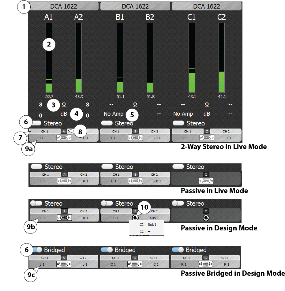
- Amplifier Model Selector – Design mode only. Click the amplifier name to display the Amplifier Selector drop-down list from which you can select the amplifier connected to that DataPort. If the amplifier you are using is not shown, select Unassigned. Fault, impedance, and attenuation monitoring are not available if the model is Unassigned.
- Amplifier Input Level Meter – Live mode only. The level meter with a digital readout below it, represents the input to the amplifier. Green – signal is good, Yellow – signal is good, Orange – signal is close to clipping, Red – signal is clipping. NOTE: When the Stereo / Bridge switch is set to Bridged, only one Level Meter is shown.
- Loudspeaker Impedance – Live mode only. Displays the impedance of the loudspeaker connected to the amplifier. There must be adequate signal present in order for the impedance to be shown. If very low impedance is detected, a Short condition will be shown. If the impedance is very high, an Open condition will be shown. If the voltage and current monitor return signals from the amplifier are both too low, no impedance is shown.
- Amplifier Attenuation – Live mode only. Displays the attenuation level of the amplifier. There must be adequate signal present in order for the attenuation to be shown. Ideally, this should be close to 0dB. If it is lower than -1dB to -2dB, check the gain controls on the front of the amplifier to make sure they are set to the maximum level.
- No Amp – Live mode only. If the voltage monitor return signal from the amplifier is very low, a No Amp condition is shown, indicating that the amp may be disconnected, unplugged or powered off by its power switch.
- Stereo / Bridged Switch – Design mode only. Click to change between Stereo and Bridged operation. Your amplifier must be physically switched to corresponding mode from its rear panel.
- DataPort Channels – Each DataPort has two channels designated CH1 and CH2. These do not change.
- DataPort Identifier – Letters A through I identify the DataPort on the rear panel of the DPM.
- Output Channel Assignment – Design mode only. DataPorts A through F are automatically assigned. The assignments for Screen Channels (A, B, C) are set based on the Screen Crossover settings on the Setting tab. The following uses the Left Screen Channel as an example.
- 2-Way Crossover = LL and LH (Left Low and Left High)
- Passive Crossover = L1 and R1 (Left 1 and Right 1)
If Passive crossover is selected, click DataPort B  to enable or disable the Sub 1 output to this DataPort. Additionally, in Passive Crossover mode, DataPort F can be disabled or assigned to the Sub output.
 - Passive Bridged Crossover = L1 and L1 (Left 1 and Left 1)
Use Bridged only if you are sending the same audio channel to both DataPort Channels (CH1 and CH2). For Screen Channels, the Screen Crossover selection on the Settings tab should be Passive Bridged. Each Screen Channel will have the same crossover, so they must also be bridged on the Amps tab and the physical amplifier. - Back Surround – DataPort E (not shown) is disabled if the Back Surround channels are turned off on the Settings tab.
- DataPorts G-I (not shown) can be used for additional sub or surround zones or to output the SLfe channel.
- Plug icon – Indicates that one or more of a DataPort's Channels is unassigned and may be assigned depending on the Crossover and Back Surround settings and the specific DataPort. See above for more information on this feature. Click the icon to see a list of available assignments. When the amplifier is in Live mode, these plug icons change to DataPort connectors and cannot be changed.
© 2016 QSC, LLC. All rights reserved.